 |
LA6NCA AM transmitter with cathode modulation |
 |
|
LA6NCA AM transmitter with cathode modulation |
|
| AM transmitter with cathode
modulationters. See my youtube video about its design and construction. |
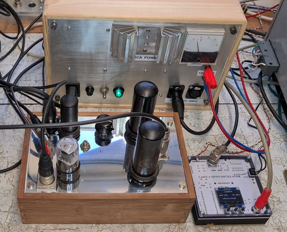
Power, Transmitter and oscillator.
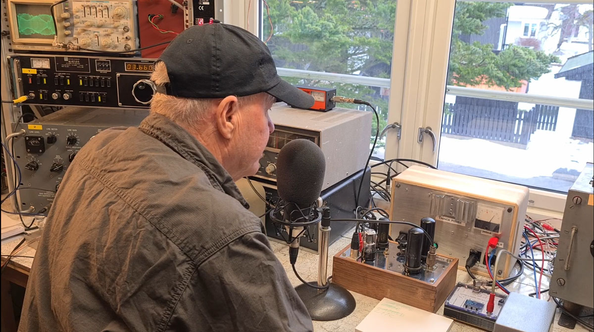
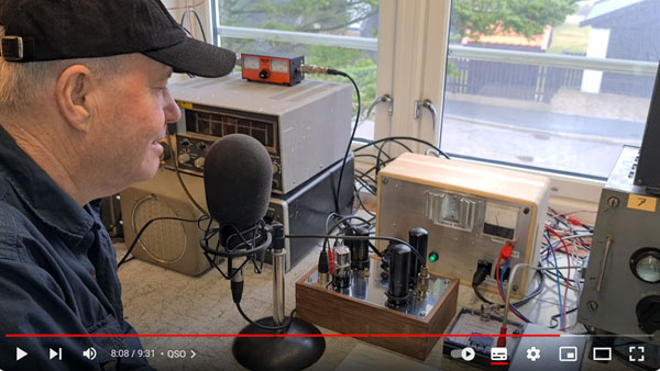
| Here I have my first QSO on AM. The transmitter is approx. 5 watts. It also has an input for a condenser microphone with 48 volt phantom power. On the left we see an oscilloscope showing the output signal. There we also see the receiver I use. |
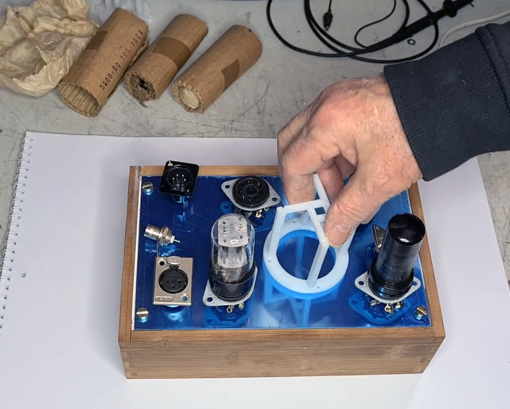
Here I have started with the mechanical work.
I design at the same time as I carry out the work.
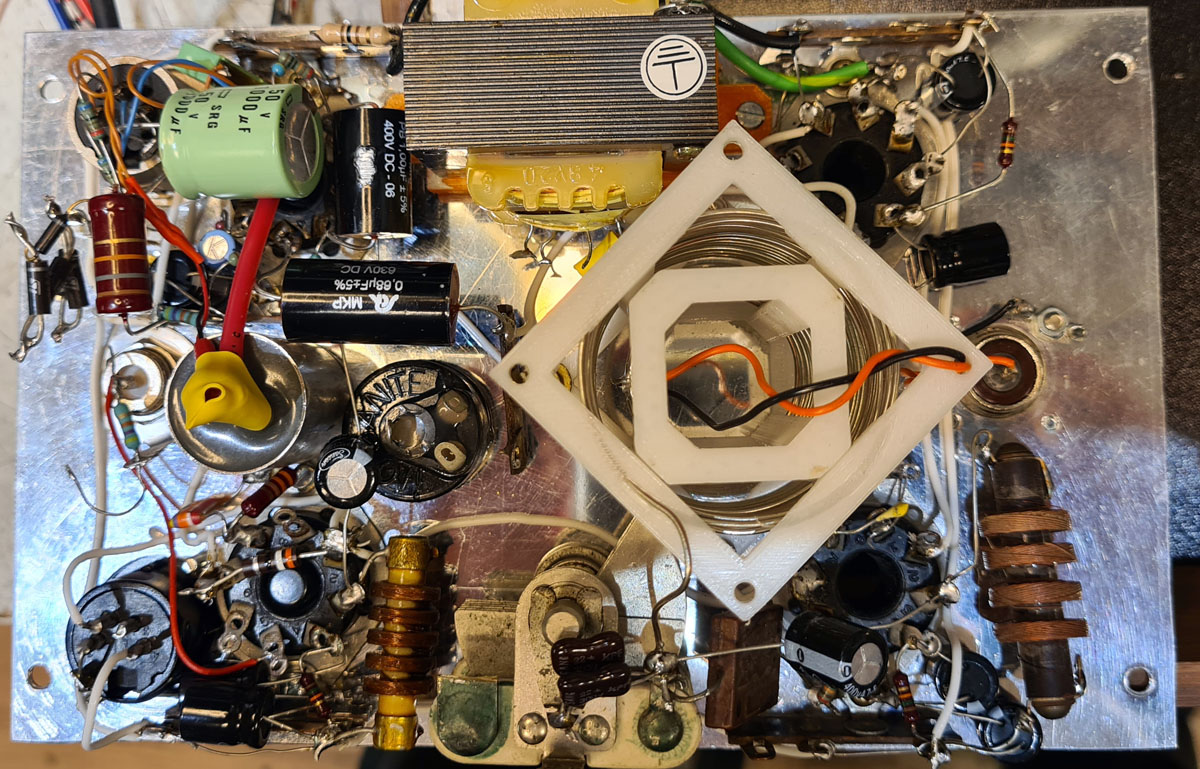
The transmitter is here finished.
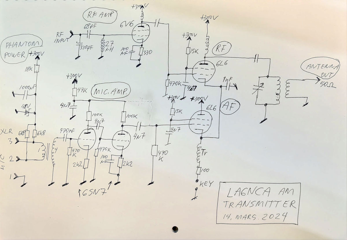
| Here we see the complete electrical
schematic. We especially see the cathode modulator with a common cathode between the RF and AF 6L6 tubes. The coil Tr in the cathode is a small mains transformer. There is also a 48 Volt phantom power input for condenser microphones. This gets power from 300 volts. |
POWER
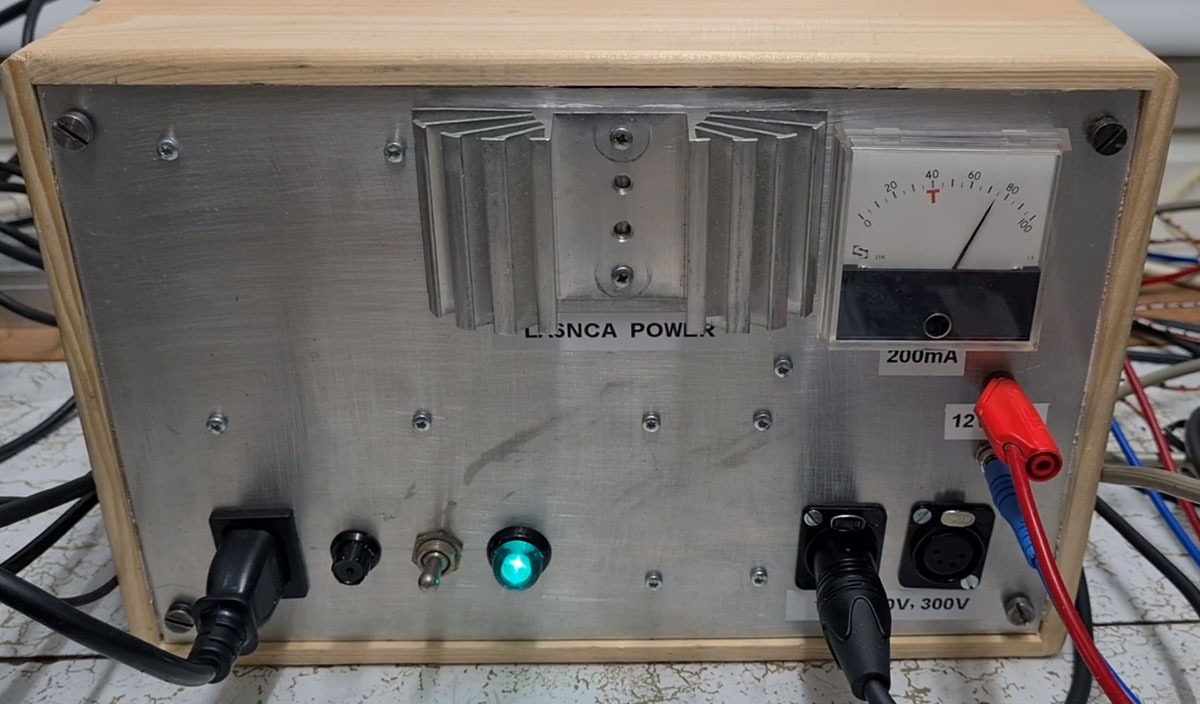
| I had to design a new power for this
AM transmitter. The total power consumption was approx. 140 mA at 300 Volts. I use a 230 Volt transformer. The voltage from this is rectified and regulated in two mosfet transistors. XLR-4 standard power connector. I have standardized my power. I use an XLR-4 connector for voltage output. Pin 1 is GND Pin 2 is 12 Volt DC heating voltage. Pin 3 is 210 Volt DC for receivers or preamplifiers. Pin 4 is 300 Volt DC for power amplifiers. Female connector for output power. |
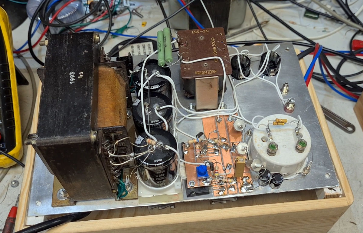
| Here we see the power inside. We note the large zener diodes for the mosfet regulators. |
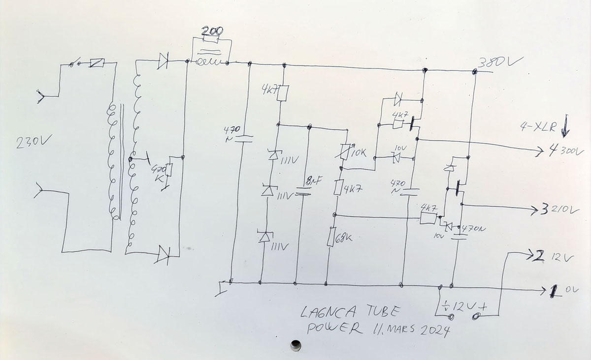
| Here we see the electrical schematic. 12 Volt DC to XLR pin 2 is taken from an external power source. The coil with 200 ohm resistance was actually designed to deliver the RMS value of the sine voltage to the regulators. But the voltage was too low, so I had to correct a bit with this 200 ohm resistor. |
VIDEO YOUTUBE
https://youtu.be/a3unRhWOgEg